Settings menu
The settings menu is divided into several sections, which are described below.
General settings
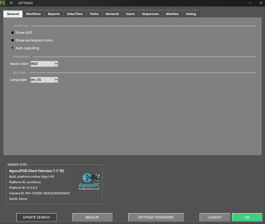
Show exif
Displays the metadata of the current image in the main workspace area.
Show workspace icons
Enable a set of features in the main main workspace area. Learn more about these features in the next section.
Auto signaling
By default, the software numbers each error after the inspection. When this option is disabled, only the affected area is highlighted in color, without a number.
Mask color
This option allows you to change the color of the marked error. When the color of the marked error matches the color of the PCBA, it's advisable to change it to a higher contrast color to make the marked areas more visible.
Language
Change the interface language. The current available languages are: English, French, German, Italian and Spanish.
Workflow options
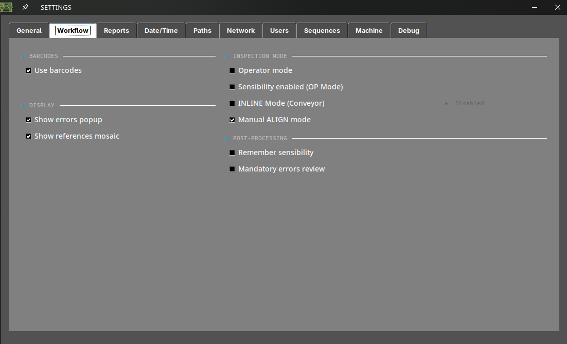
Use barcode
Toggles the barcode reading function
Show errors popup
By disabling this option, the reporting window will no longer pop up when reporting an error with the UP or DOWN arrow keys. The reported errors will be generated with the "other" label in the final PDF report.
Show references mosaic
By disabling this option, the mosaic menu won't pop up after taking a REFERENCE image.
Operator mode
Enabling this option will hide several features from the interface, simplifying the software's use. It also prevents the operator from changing the REFERENCE image or the sensitivity of the inspections. A password can be added so that only the administrator can disable this option.
Sensitivity enabled
It allows you to change the sensitivity while in operator mode.
INLINE Mode
Select this mode when the AOI is installed on a conveyor belt. Learn more about this functionality in the following section: Production line integration
Manual align mode
Enable this option to align the REFERENCE and UUI images manually. Learn more about this functionality in the following section: Manual alignment tool
Remember sensibility
By activating this option, the software will maintain the configured inspection sensitivity after performing a new inspection.
Mandatory errors review
If this option is enabled, the software will not continue inspecting new panels until all errors detected in the current inspection have been reported as errors or false positives.
Report options
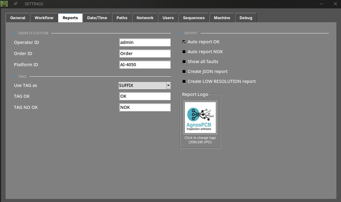
Operator ID
Set an ID for the current operator. This ID will be displayed in the final PDF report after the inspection is complete.
Order ID
Set an ID for the current manufacturing order. This ID will be displayed in the final PDF report after the inspection is complete.
Platform ID
Set an ID for the AOI.
Use TAG as
Set the TAG (OK or NOK) of the final PDF report as a suffix or a prefix to the file name.
TAG OK
Set a custom OK TAG for the final PDF report.
TAG NO OK
Set a custom NO OK TAG for the final PDF report.
Auto report
When this option is enabled, a final PDF report labeled OK will be automatically generated if no errors are detected after the inspection. The final PDF report can also be generated if any errors are detected during the inspection.
Note
When generating a PDF report automatically, all errors detected will be marked with the "unknown" label.
Show all faults
Displays all detected errors in the PDF report even if the operator has not reported them.
Create JSON report
Generates a machine-readable JSON file with the inspection data, in addition to the PDF report. Use this option when the results have to be processed by another system — an MES, an ERP or a traceability database — instead of being read by a person.
The JSON file is written to the same folder as the PDF report, inside the PCB OUT directory.
Note
This is a licensed feature. If the option does not generate any file, contact support@agnospcb.com to check whether your account profile includes it.
Create LOW RESOLUTION report
Generates an additional PDF report with a reduced file size. The standard report is still generated: this option adds a lighter copy of it, it does not replace it.
This is useful when the reports have to be sent by email, archived long term, or transferred over a slow or metered connection, where the full resolution images would make the file impractically large.
Logo
Set a logo for the PDF report.
Date/time options
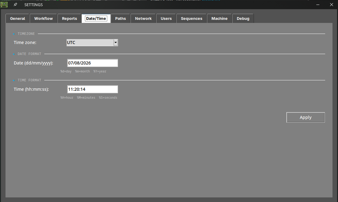
Time zone
Set the time zone.
Date and time
Set day and time.
Note
To apply the changes press the SET button and reboot the system.
Path option
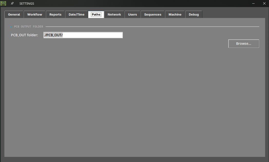
PCB OUT
Change the path where the inspections are generated.
Share options
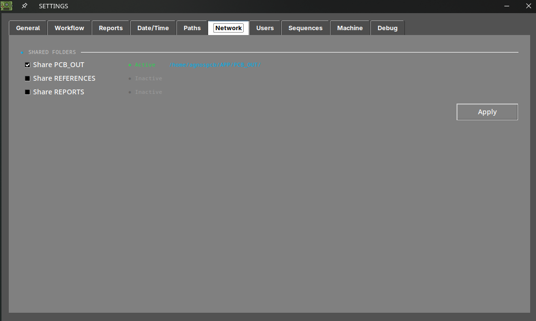
Share folders
By enabling these options, the system will automatically share the PCB_OUT and REFERENCE folders on your local network. The access address will be displayed once the option is set.
Note
To apply the changes press the Apply button.
Note
For the OFFLINE units, if you need to change the network interface of your unit, please refer to the network configuration article.
Users
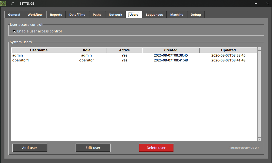
This tab is only available to users with the admin role. It allows you to create the accounts that can operate the AOI, each one with an admin or operator role, and to require a username and password every time the software starts.
Enabling Enable user access control requires at least one active admin account to exist.
Learn more about this functionality in the following section: User access control
Sequences
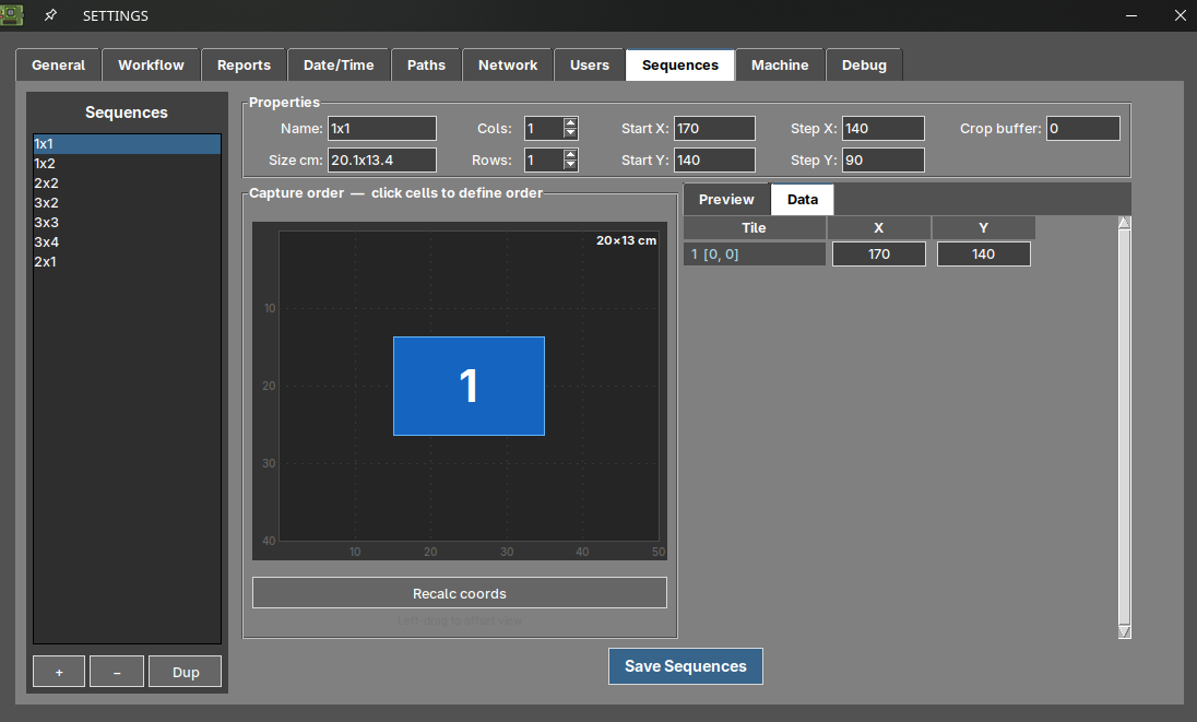
This tab is only available to users with the admin role. It allows you to define your own capture sequences, that is, the grid of photographs the camera takes and stitches together to compose the image of a large board.
Use it when none of the predefined sequences fits your board properly. The sequences you save here appear as CUSTOM options in the live preview window when taking a REFERENCE or starting an inspection.
Learn more about this functionality in the following section: Custom capture sequences
Note
This tab is not displayed on units configured in Q1 mode, which only take a single capture.
Machine
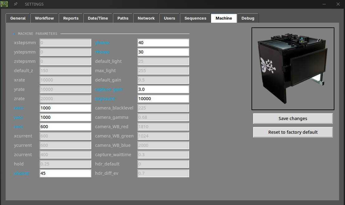
This tab is only available to users with the admin role. It displays the hardware parameters of your unit, stored in the machine.json file.
Most of the values are shown grayed out: they are displayed for reference only and cannot be modified. The fields highlighted in blue are the editable ones:
| Field | Description |
|---|---|
| xacc / yacc / zacc | Acceleration of each axis. |
| xhome / yhome / zhome | Home position offset of each axis. |
| capture_gain | Camera gain during the capture. |
| exposure | Camera exposure time. |
Press Save changes to apply the new values, or Reset to factory default to restore every parameter to its original value.
Important
These parameters affect how the platform moves and how the images are captured. Modifying them incorrectly may degrade the image quality or the movement of the axes. Change them only when support asks you to.
Note
This tab is not displayed on units without an XYZ platform.
Debug
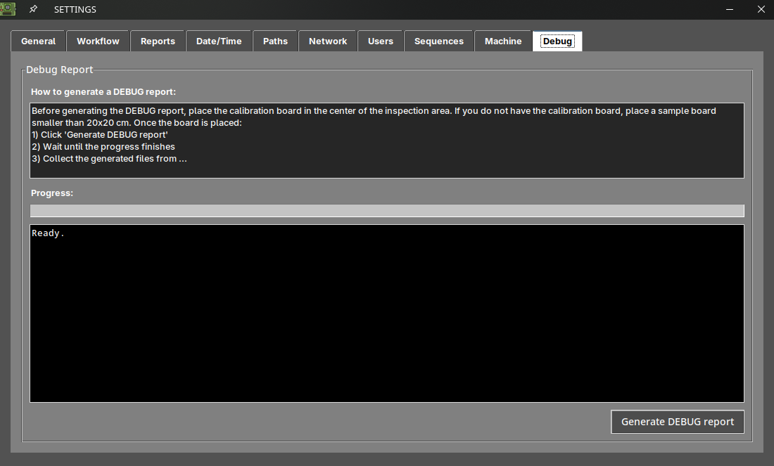
This tab is only available to users with the admin role. It generates a diagnostic report that allows our support team to analyze the behavior of your unit.
To generate it:
- Place the calibration board in the center of the inspection area. If you do not have it, use a sample board smaller than 20x20 cm.
- Press Generate DEBUG report.
- Wait until the progress bar is complete. The text area below displays the progress of the process.
- Collect the generated files and send them to support@agnospcb.com.
Info section

AOI info
The AOI information is displayed in this section.
Backup
This function generates a backup compressed file of the PCB_OUT folder automatically. The backup file is stored in the APP/BACKUP folder.
Settings password
Set a password to access the settings menu.
Note
Set the password to blank to disable the password requirement.